HOPG
Highly ordered pyrolytic graphite
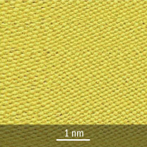
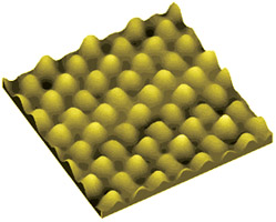 Atomic lattice of graphite (HOPG). Image size 1.7×1.7×0.2nm (ATC, Scan-8). Courtesy of Advanced Technologies Center (www.nanoscopy.net).
HOPG - Highly Ordered Pyrolytic Graphite is the material produced by the application of uniaxial pressure on deposited pyrocarbon at very high temperatures (sometimes more than 3000oC). Depending on deformation, temperature and annealing time one can get material with different mosaic spreads, amounts of defects and granular structures (average size of the grains and crystallites). The most suitable HOPG for STM/AFM applications should have large grains and crystallites, a uniform surface with minimal steps (parts of broken carbon planes) and should allow easily cleaving of very thin layers, such that the surface of the sample can be refreshed many times for investigations.
Hopg structure
 Positional relationship between two identical graphene planes A and B. Graphite structure can be described as an alternite succession of these planes ...ABABAB...
Graphite belongs to lamellar materials and consists of identical staked planes. Carbon atoms within a single plane interact much stronger than with those from adjacent planes. That explains the lamellar behavior of graphite. Each atom within a single plane has three nearest neighbours. The network of carbon atoms connected by shortest bonds looks like honeycomb. This two-dimensional and single-atom thick plane is called "graphene".
"Typical" graphite, especially natural one, exhibits quite imperfect structure due to plenty of defects and inclusions. A number of technologies are developed for preparation of perfect graphite samples to take advantage of its unique structure. Of these, pyrolysis of organic compounds is the most common and effective.
To characterize perfection of HOPG samples, one uses the term "mosaic spread" which originates from X-ray crystallography. Similar to mica, HOPG specimens are layered polycrystals resembling a mosaic of microscopic monocrystal grains that are slightly disoriented with respect to each other. The disorientation of the graphene sheets is responsible for the broadening of the (002) diffraction peak.
How is HOPG made?
According to the nature of graphite, higher annealing temperatures and longer annealing times reduce the number of defects in the material and allow it to approach “ideal” graphite. In principle, mosaicity, defects and granular structure may vary independently when annealing parameters change. But in the frame of the standard technology of HOPG production, a correlation between mosaic spread, defects and granular structure exists. Therefore, samples annealed at higher temperatures have lower mosaicity and a more ”ideal“ structure.
Annealing at 3000ºC under high pressure is a very complicated technological process, which imposes some restrictions on the annealed volume and causes a significant temperature gradient especially in the vicinity of the pressing pistons. As a result, the quality of the material is best at the center of the annealed volume where the highest temperature is achieved, while the amount of defects as well as mosaicity increase towards the outer part of the annealed plate, so that the external part that directly contacts the piston (the last 0.5-0.7mm) could hardly be called HOPG at all.
Due to historical and price reasons, samples cut near these external regions (near the pistons) were used until recently for STM/SPM applications, while the inner part of the annealed volume (plate) was used mainly for neutron and X-ray monochromators.
Characterization of MikroMasch HOPG
The mosaic spread is characterized by measuring (in degrees) a full width at half maximum (FWHM) of the rocking curve (Cu-Kα radiation peak).
Mosaic spread is measured by the standard method. Measurements are carried out with Cu-Kα radiation and the beam illuminating a significant part of the crystal simultaneously (approximately 8 X 8 mm taking into account the incident angle). This is important because the measured value of the mosaic spread depends not only on crystal quality, but also on the energy and the cross section of the reflected beam. This effect is caused mainly by large-scale surface inplanarity or large-scale inplanarity of the carbon layers. Small regions tested by a narrow beam could have additional mutual mismatch that increases the measured value of mosaic spread when the crystal is illuminated by a wide beam covering both regions simultaneously. In a similar way the large-scale mismatch between outer layers and deeper layers that start to involve reflection could increase the value of mosaicity measured with harder X-rays or with neutrons which have a larger penetration depth than Cu-Kα radiation.
|
HOPG
Grade |
Mosaic
Spread |
Spread
Accuracy |
Side | Thickness |
Chip
Size |
Application |
| ZYA | 0.4° | ±0.1° | Double | 1 & 2mm | 10×10mm | X-ray optics, SPM calibration, SPM substrates |
| ZYB | 0.8° | ±0.2° | Double | 1 & 2mm | 10×10mm | SPM substrates |
| ZYH | 3.5° | ±1.5° | Double | 1 & 2mm | 10×10mm | SPM substrate in non-critical work, training |
Double-sided samples
 One of the first images of graphite atomic structure, obtained on FemtoScan microscopes Courtesy Advanced Technologies Center (www.nanoscopy.net) *Not for calibration of X-ray equipment.
Samples cut from the center of the annealed volume of HOPG that have the same mosaic spread throughout are called double-sided. To confirm the grade, the mosaic spread is measured on both sides of the sample. In such samples there is no degradation of quality through the sample, thus the quality of the freshly cleaved surface remains identical during the thinning of the sample. The thickness of the cleaved layers does not increase with the number of cleavings, so one can refresh the surface more times than with single-sided samples.
STM/AFM applications
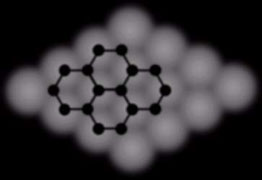 Typical STM image of HOPG surface. Corresponding fragment of graphene structure is superimposed.
HOPG terminated with graphene layer can serve as an ideal atomically flat surface to be used as a substrate or standard for STM/AFM investigations. This is also an easily "cleavable" material with a smooth surface, which is vital for SPM measurements that require a uniform, flat, and clean substrates.
X-ray
Due to the good quality confirmed by precise X-ray control, our HOPG can be used not only as an STM substrate, but also as crystal-monochromators for X-rays and neutrons (nevetheless, it is important to inform us in advance that certain samples are going to be used as monochromators – we will choose crystals with better planarity from a batch).
Videos