Characterization and Calibration of MFM Tips. Quantitative Measurements in Magnetic Force Microscopy
Theory basics
Since the majority of all Scanning Probe Microscopy techniques is based on the force or force derivatives detection, the starting relation is:
![]()
where Etip-sample is the energy of tip-sample interaction.
Particularly for Magnetic Force Microscopy Etip-sample can be expressed in terms of a convolution of the tip magnetization Mtip and a stray field from the sample Hsample or, vise versa, as a convolution of the AFM tip stray field Htip and the sample magnetization Msample:

where integration is performed over the whole magnetic volume of the AFM tip (first relation) or the sample (the second one). In case of no perturbation between the AFM tip and the sample both approaches should give equal results.
Therefore, generally speaking, having measured forces (or their derivatives) acting between the tip and the sample, it is theoretically possible to restore the AFM tip magnetization distribution Mtip if the stray field from the sample Hsample is known in detail. Then, using such a calibrated AFM tip with known Mtip one can extract stray field distribution from an unknown sample with the help of an MFM scan. Vise versa, upon some model assumptions on the distribution of the stray field from an MFM tip Htip and having assessed this value numerically, one can restore the magnetization distribution Msample within an unknown sample. At the same time, care should be taken in interpreting stray fields out of the media emanating them because exactly the same outer distribution of the magnetic field can be generated with different bulk conditions [1174].
In most cases, and for MFM in particular, tip-sample interaction is substantially one-dimensional and consideration of only the z-component of the force derivative F'z gives satisfactory numerical estimations:
![]()
By now the phase shift detection scheme is most widespread for force gradient mapping in MFM because the phase shift is proportional to the force derivative F':

Besides one-dimensional approximation, a number of other simplifications are made due to the complexity of the problem of magnetic interactions.
First, the real distribution of magnetization Mtip in the MFM tip can only be guessed. Therefore, some simplified models have been proposed to replace the real AFM tip with an appropriate approximation.
There are two most commonly used approaches developed to date: the point probe model [2649] and the extended (magnetic) charge model. There is a number of implementations of these two methods.
The point probe model assumes that the magnetic AFM tip can be replaced with a single magnetic pole of monopole q or dipole m nature, one being a constant scalar and the other - a constant vector (Fig. 1, a).
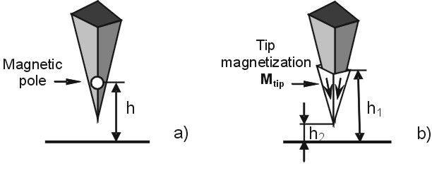
Fig. 1. Schemaic representation of the two most commonly used models of MFM tip. a) Point probe model. The MFM tip is approximated by a single point pole of monopole q or dipole m nature. b) Extended charge model. One of the model implementations is shown. MFM tip is approximated by a pyramid with different magnetization vectors on different facets. The active imaging volume is depicted in white. See also Fig. 3.
The expression for the monopole approximation can be written as:
![]()
and for the dipole approximation as:

where Meff is the effective uniform AFM tip magnetization and Veff is the effective imaging volume of the AFM tip.
Combining both contributions the resulting force in one-dimensional case can be expressed as:

and the force derivative as

As a matter of fact, the point pole approximation is rather rough due to the above simplifications, and fails to explain the entire stray field from the AFM tip [2604]. The advantage is that the field calculation is simple and application to the theory of MFM is straightforward. This approach is continuously being applied by many researchers.
The extended charge model which assumes that magnetic charges in the AFM tip volume are nonpoint like (Fig. 1, b) looks much more realistic. Unfortunately, implementations of this model are more complicated. Working in the Fourier domain helps to simplify calculations in this case.
Both models become inaccurate if the samples with characteristic dimensions of the magnetic features different from those used for calibration are investigated. So far, neither model is able to guarantee "absolute" calibration of the given AFM tip. Thus, recalibration for various samples is necessary.
Limitations of current magnetic force imaging techniques give rise to refinement of existent theoretical backgrounds and development of novel experimental approaches such as the one described by Schaffer et al. [2597]. The process to find out reliable and universal quantification in MFM continues.
It should also be taken into consideration that the measured MFM signal is a convolution of the so-called instrumental response function and the pure MFM signal. Therefore, in roder to extract the pure MFM signal specific deconvolution procedures should be performed. This effect becomes larger as the magnetic features on the sample surface are reduced.
Experimental techniques
A number of approaches have been proposed to acquire both qualitative and quantitative description of magnetic AFM tips in order to make MFM imaging quantitative. These approaches can be divided into two main groups: techniques based on MFM scanning over current carrying structures formed on a calibration sample surface and the rest which use other principles involving MFM for successive correction of the initial approximations or do not use MFM at all.
The second group comprises Resonant Torque Magnitometry (RTM) [2633, 2621], Lorentz electron tomography [2603], electron holography [2664] and some other methods.
These methods help understanding peculiarities of the magnetic field distribution in the nearest vicinity of the magnetic tip and are to be considered as independent ways to develop a reliable and simple MFM-like method of AFM tip characterization/calibration.
Resonant Torque Magnetometry allows a hysteresis loop to be obtained by applying a local field to the AFM tip, either along the AFM tip axis or normally to it, and measuring torque response of the AFM tip [2621]. Sensitivity better than 10-12 emu (10-15 A·m2) is reported by Heiydon et. al [2633]. Measurements are performed in-situ that is of great importance especially when images are made in the presence of bias fields. At the same time this technique is rather exotic and cannot be implemented in common laboratories. RTM also imposes some limitations to the measuring conditions.
Lorentz electron tomography used by McVitie et al. [2603] registers the deflection of an accelerated electron beam influenced by the magnetic field in the nearest vicinity of the MFM tip (Fig. 2).
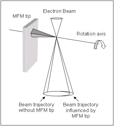
Fig. 2. Schematic of the differential phase contrast imaging technique of Lorentz microscopy applied to a MFM tip (McVitie et al. [2603]). This imaging mode is implemented on a scanning transmission electron microscope.
This technique gives the real, but integral field distribution near the AFM tip apex not distorted by any external fields. The data obtained easily reveals anisotropy of the field around the axis of the AFM tip due to its nonideal pyramidal form. A small tilt over the measured surface as well as some unwanted effects ([2663]) also contribute to the final result. Then, specific tomographic reconstruction is implemented to restore the real field distribution. The authors compare data obtained by electron tomography with the results of calculations according to most common approximations of the MFM tip magnetic state such as the point pole and extended charge models. It is found that the field from the MFM tip has contributions which are point like and nonpoint like. While the central part of the field can be well represented by a point or localized charge, the modeling of extended tails of the field implies nonlocal magnetic charge distribution. The profile of magnetic field using the extended charge model (Fig. 3) can be ideally fitted by means of fitting parameters. There are, though, some difficulties in the interpretation of thus obtained results.
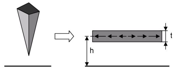
Fig. 3. Representation of MFM tip by magnetic layer of thickness t with predefined magnetization distribution according to extended charge model used by McVitie et al. [2603] for Fourier space calculations.
Another technique involving multiple MFM sessions and Fourier transforms is developed by Hug, van Schendel et al. [2632, 2604]. It is a sophisticated iterative procedure for MFM tip calibration using a transfer-function approach. The sample under scanning is a special sandwich-like Cu/Ni/Cu structure with strong perpendicular magnetization. The authors come to the conclusion that the point monopole and dipole models of the MFM tip are not suitable to describe the tip calibration found in the experiment. And in spite of the fact that a reasonable agreement between the simulation and the measurement is obtained with a monopole model with additional tip-sample distance, it is not recommended to use the point pole model for the evaluation of MFM data acquired on a sample with domains with a different size than those of the sample used for calibration. Even using the extended charge model the tip should be recalibrated to investigate samples with magnetic feature sizes different from the ones used for calibration. The authors find the point pole probe approach inadequate when interpreting submicron magnetic features which are comparable to the AFM tip size, though this approach may still be applicable for structures with relatively large features and large lift heights. The maximum magnetic flux density at the AFM tip end was estimated about 0.01 Tesla for about 10nm Fe layer covered with ~15nm Au coatings. The sensitivity is found to be in the microtesla range for stray field variations on the order of 100 nm.
By common practice, determination of a sample stray field using a calibrated MFM tip of given magnetization Mtip is the most often task investigators have to encounter. This task is successfully solved using MFM tips calibrated by means of the first group techniques. It is obvious, that only current carrying metal stripes are able to produce well-controllable and regular magnetic field with predefined distribution Hsample to restore AFM tip magnetization Mtip. Due to micron and submicron scales these stripes are manufactured by electron beam lithography and may differ in geometry. The following types of strip lines are reported so far: one straight strip line [2582, 2619]; two or more straight strip lines [2599, 2600, 2631, 2634, 2635, 2639], current rings [2612, 2636, 2637].
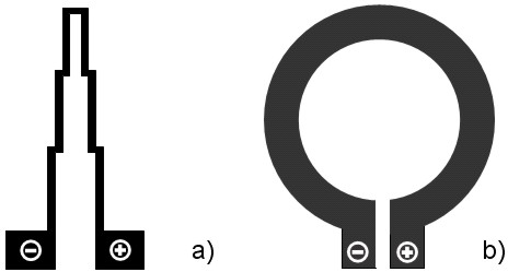
Fig. 4. Typical current strip line configurations for generating a well-defined magnetic field. a) Two parallel strip lines with regions of various distance between lines (Goddenhenrich et al. [2631]). b) Current ring (Kong and Chou [2636, 2637], Lohau et al. [2612]).
The first attempt to compare calculated and measured magnetic forces acting between an AFM tip and a sample using current carrying strip lines is undertaken by Goddenhenrich et al. [2631] in early 90-s (Fig. 4, a). The authors achieve satisfactory qualitative agreement of calculated and measured curves. To obtain semiquantitative results convolution effects due to finite AFM tip size should be also taken into consideration.
The distribution of magnetic field gradient for a couple of straight lines is shown in Fig. 5.
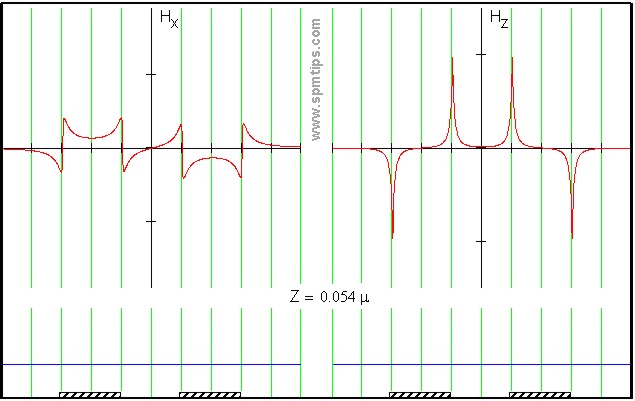
Vid 5. Distribution of the horizontal (Hx) and the vertical (Hy) components of the magnetic field gradient over two current carrying strip lines of opposite polarity upon height Z in microns. The lines go in parallel to each other and only their cross sections are shown. Both components are plotted separately for convenience. One can see that distribution of Hx component is symmetrical relative to the strip line profile, and that of Hz is antisymmetrical. After viewing the full animation it is obvious that the distribution of Hx component changes drastically upon vertical distance Z as opposed to Hy which changes in amplitude only.
Yongsunthon et al. [2599] consider MFM a useful method for studying electromigration in metals which is of vital importance due to the continuous shrinkage of integrated circuit dimensions. Their proposed calibration structure comprises three metal strip lines (Fig. 6), of which the left is a null-potential grounded line connected to the AFM tip, the central line includes a small slit in the central part thus modeling a defect, and the right line is a reference one with well defined geometry.
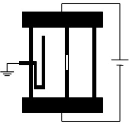
Fig. 6. Current strip line configuration used for in situ calibration of MFM tips by Yongsunthon et al. [2599].
The null-potential line guarantees the absence of an electrostatic component among the various tip-sample interactions. It serves to indicate that no phase shift is present when the AFM tip is scanning above this area. The reference structure is used to normalize the signal magnitude from the test structure. Also it is intended to determine iteratively the so-called instrumental response function which enables deconvolution of the measured MFM signal in order to extract the pure MFM response. Using the dipole moment approximation in accordance with the point probe model, relative quantification of the MFM signal amplitude to within 10% can be achieved and absolute current variations can be detected to at least 10%.
Successful application of MFM imaging to map quantitatively current densities around various defects in metal conductors is reported in work by Yongsunthon et al. [2639] and Rose et al. [2600].
Results presented lately by Kebe and Carl [2634] reflect the progress made for more than a decade in MFM tip calibration using current carrying structures. Beginning from current rings in early works, the authors consider various parallel wire configurations in this ample paper. Analysis is again conducted using the point probe model for approximation of the MFM tip. Having studied many configurations of current carrying lines authors related point probe parameters to the dimensions of parallel wires and to the characteristic decay length of the z-component of the magnetic field produced with them. This allowed to determine the effective volume Veff of the real magnetic AFM tip relevant in MFM imaging. The authors proposed an experimental technique which allows quantitative measurements of the magnetization of nanoscale ferromagnetic elements with in-plane magnetization by a calibrated MFM tip.
Kong and Chou pioneer the use of current rings for MFM tip calibration purposes [2636, 2637]. Using monopole and dipole approximations within the point pole model the authors find that at different lift heights both moments contribute unequally, which gives rise to the final conclusion that only the dipole moment is relevant for imaging.
Lohau et al. [2612] thoroughly study the applicability of the point pole model to the quantitative determination of the magnetic state of the AFM tip using current rings of various radii. It is found that MFM images can only be analyzed unambiguously within the point pole approximation when using either the dipole or the monopole contribution taking into account heights of the point pole above the sample surface which are different in each case. Both point probe approaches are found to give identical results independent of the lift height used and it is therefore not necessary to consider a mixture of both contributions.
A number of papers describe changes in the magnetization of MFM tips imposed by external magnetic fields. The use of current carrying structures becomes here the only way to determine the AFM tip's magnetic state because any other magnetic sample is critically affected under strong fields applied, whereas the stray field from such current carrying structures is kept unchanged. Knowing the magnetization reversal of the AFM tip, the magnetization reversal of magnetic samples can be studied.
Typical hysteresis loops for AFM tips of various shape and covered with various coatings are presented in Fig. 7.
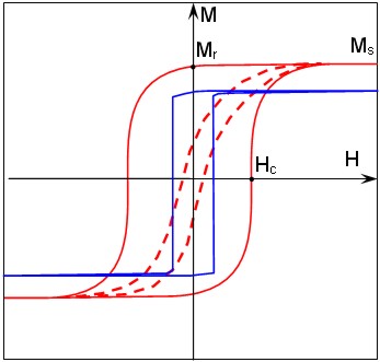
Fig. 7. Typical hysteresis loops obtained for various metal coatings of MFM tips. The high coercivity coating has a broad hysteresis loop (solid red line). The low coercivity coating has a narrow loop (dashed red line). The blue line reflects the behavior of a coating deposited on narrow and long tip. This coating switches as a single domain particle under a varying external field and features an almost square hysteresis loop. Hc, Mr and Ms stand for coercivity, remanent magnetization and saturation magnetization respectively.
In general, magnetic coatings can be divided into two categories: made of high coercivity (CoCr, CoCrPt etc.) and low coercivity (FeNi, FeCoNi etc.) materials. There are also reports about superparamagnetic [2730, 2567], paramagnetic [2705], antiferromagnetic [2711] or multilayer [2691] MFM tips. The proper choice depends upon the purposes of a given study. It is found experimentally that the typical coercivity of CoCr tips is between 300 and 400Oe, and for low-coercivity tips Hc amounts to 1-5Oe or even less.
It should be remembered, that high coercivity AFM tips may influence the sample magnetic structure and vice versa. Such perturbation leads to displacement of domain walls [2615, 2748, 2749], irreproducibility of successively taken images [1111, 1122], and other unwanted effects. As for imaging in applied external magnetic fields, it is desirable to use an AFM tip either having coercivity far beyond that of the sample (so that the applied field does not affect the AFM tip), or far below it (so that the AFM tip moment is always aligned with the applied field) [2582]. Tapping the sample with the MFM tip during topography acquisition in interleave or "liftmode" may significantly perturb magnetization distribution in the sample or in the AFM tip. Therefore, if sample topography is sufficiently smooth, noncontact imaging at fixed height is preferable instead of a two-pass technique such as liftmode.
The higher the aspect ratio of the AFM tip, the more uniform and predictable is the magnetization distribution in the volume of the magnetic coating. The utmost case is a narrow needle shaped AFM tip proved to be monodomain, so that its hysteretic loop is of almost square shape (the so-called coefficient of squareness is close to 1.00).
Babcock et al. [2582] systematically study the magnetic states of a set of MFM probes as a function of a uniform external magnetic field using a single current strip line. In order to avoid influence of electrostatic forces the entire structure is covered by thin insulating and metal coatings, the latter being grounded during MFM measurements. It is shown that there are two different response characteristics for lateral and vertical components of remanence magnetization in the phase images. The vertical component gives antisymmetric response and the lateral - a symmetric one. Such an effect is easily seen from the field gradient profiles, plotted in Fig. 5. The authors show that after magnetizing even in strong lateral fields remanence state is apparently far from horizontal orientation but tilted 30-40° relative to the plane of the sample.
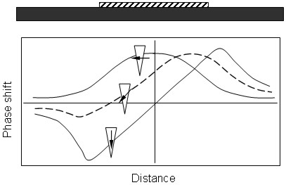
Fig. 8. Responses of an MFM tip scanning a single strip line (shown above) under various orientations of the external field (according to Babcock at al. [2582]).
Carl et al. [2569] describe an experimental technique to determine the magnetization reversal and coercivity of MFM tips using a current carrying metal ring. Measurements are conducted in the central part of a substantially large (Ø=2400nm) ring. Such a big size guarantees that mainly a vertical Hz component is present in the central part of the ring and there are no electrostatic forces present in this area and therefore a shielding metal coating is not exploited. The coercivity Hc, remanence magnetization Mr, and saturation magnetization Ms of the AFM tips from corresponding hysteresis loops are obtained varying the external field from Hz to -Hz.
It is found that the properties of theoretically identical AFM tips from various wafers differ widely, sometimes by a factor of 2. This discrepancy can only be attributed to unequal manufacturing conditions rather than to other reasons. The typical coercivity for CoCr coated AFM tips is found to be within 270-360Oe and remanence magnetization Mr=869-1336emu/cc. For comparison the same characteristics are gathered by Superconducting Quantum Interference Magnitometry (SQUID Magnetometry). Values obtained by SQUID measurements differed from those of MFM widely. For example, Hc,SQUID/Hc,MFM relation lie within 0.9-2.2 range. It is only MFM that allows estimation of the volume of the AFM tip relevant for image formation. Therefore, the choice in favour of MFM rather than SQUID magnetometry is preferable to assess the most common magnetic properties of the AFM probing tip.
Using an AFM tip calibrated in such a way Lohau, Carl et al. [2602] determine quantitatively the hysteresis loop of a single magnetic dot of 230 nm in diameter taking into account the correction for the AFM tip reversal properties. The technique described in the paper allows to measure precisely the coercivity of a given sample Hc,sample even if it is comparable with the coercivity of the AFM tip itself. Furthermore, the shape of the hysteresis loop of small magnetic elements may be obtained with sufficient accuracy in order to be able to differentiate, e.g., between different reversal modes of magnetic elements.
In conclusion, some general regularities are given concerning resolution and sensitivity in MFM measurements.
AFM probe sensitivity over the current strip line can be estimated in terms of the minimal magnetic moment within the point dipole approximation:

where fo is resonance frequency shift. For example, in the case of the most commonly used CoCr coatings mz ~6·10-12emu has been reported [2582].
MFM resolution and magnitude of the contrast observed in MFM depend upon the geometry and size of the magnetic material which interacts with the sample stray field. This functional part is also called the "active volume" of the MFM tip (depicted in white in Fig 1b). Both resolution and contrast for "magnetically hard" MFM probes increase if the final portion of the AFM tip longer, narrower and with a flat end [2645]. Such AFM tips are manufactured using Electron Beam Deposition [2643, 2728] or Focused Ion Beam [2647, 2691] techniques. At the same time it should be remembered that such AFM tips are easily worn during tapping while acquiring topography by means of the widely used two-pass technique. Hence, non-contact mode is preferable if no great topography variations are present on the sample surface.
The horizontal and vertical resolution of MFM imaging differ greatly. Commercial AFM tips are intended mainly for sensing the vertical field component whereas in-plane components are often out of their capabilities. To make the AFM tip sensitive to lateral forces, the very end of the AFM tip must be magnetized horizontally. Simply applying an external magnetic field in the horizontal direction will give little success. The remedy could be to manufacture a nanoscopic pinhole in the very apex of the magnetic AFM tip as offered by Folks et al. [2610]. This leads to the presence of a very small region with a sufficiently strong horizontal magnetic moment. Another three- step way to extract information about distribution of lateral magnetic moments from MFM scans is described by Zhao et al. [2648].
Abelmann et al. [1108] report results of a significant study devoted to comparing the resolution of MFM from various manufacturers using special reference samples consisting of CoNi/Pt magneto-optic multilayers with different thicknesses. It is found that resolution does not vary considerably between the different instruments and lies within the 30-100nm range. Theoretical analysis sh ows that the maximum resolution is governed by the distance between the magnetic charges in the sample and in the AFM tip, which is quite different from the physical tip-sample separation. The lower the separation the higher the resolution. Though, reduction of the physical tip-sample separation leads to a plenty of smaller details or even artefacts of nonmagnetic origin. Therefore, reduction of the magnetic rather than the physical distance between the interacting charges becomes a matter of art.
Dependence of MFM data on the AFM tip magnetization orientation is studied by Litvinov and Khizroev [2709], who manufacture a fine cylindrical MFM tip with a 50nm diameter and a 10nm height which is one of the best ever reported physical implementations of the "dipole moment" MFM probe. By controlling the preferred orientation of the magnetization, it is possible to define directional sensitivity. The preferred orientation is controlled either by choosing a proper magnetic material with preferred crystalline anisotropy or by applying a sufficiently strong external magnetic field.
A complete list of references to the articles devoted to MFM-related problems is placed in the Reference Collections section of our Library.
Please, send all comments and suggestions concerning these pages to info@mikromasch.com.
| ID | Reference list (newly come references are marked red) |
| 2649 | The point dipole approximation in magnetic force microscopy U. Hartmann Phys. Lett. A, 137 (1989) 9, 475-478 |
| 2631 | Probe calibration in magnetic force microscopy T. Goddenhenrich, H. Lemke, M. Muck, U. Hartmann, and C. Heiden Appl. Phys. Lett., 57 (1990) 24, 2612-2614 |
| 1185 | The influence of experimental parameters on contrast formation in magnetic force microscopy F. Kaisinger, H. Starke, G. Persch, U. Hartmann, F. Krause Thin Solid Films, 264 (1995) 2, 141-147 |
| 1185 | The influence of experimental parameters on contrast formation in magnetic force microscopy F. Kaisinger, H. Starke, G. Persch, U. Hartmann, F. Krause Thin Solid Films, 264 (1995) 2, 141-147 |
| 1120 | High-resolution magnetic imaging based on scanning probe techniques U. Hartmann Journal of Magnetism and Magnetic Materials, 157-158 (1996) 545-549 |
| 2664 | Quantitative magnetometry using electron holography: field profiles near magnetic force microscope tips D.G. Streblechenko, M.R. Scheinfein, M. Mankos, K. Babcock IEEE Trans. Magn., 32 (1996) 5, 4124-4129 |
| 1135 | Magnetic force microscopy images of high-coercivity permanent magnets L. Folks, R. Street, R.C. Woodward, K. Babcock Journal of Magnetism and Magnetic Materials, 159 (1996) 1-2, 109-118 |
| 2582 | Field-dependence of microscopic probes in magnetic force microscopy K. L. Babcock, V. B. Elings, J. Shi, D. D. Awschalom, and M. Dugas Appl. Phys. Lett., 69 (1996) 705-707 |
| 1122 | Interactions between soft magnetic samples and MFM tips S.L. Tomlinson, A.N. Farley, S.R. Hoon, M.S. Valera Journal of Magnetism and Magnetic Materials, 157-158 (1996) 557-558 |
| 2730 | Superparamagnetic magnetic force microscopy tips P. F. Hopkins, J. Moreland, S. S. Malhotra, S. H. Liou J. Appl. Phys., 79 (1996) 8, 6448-6450 |
| 2650 | Quantitative Magnetic Field Measurements With The Magnetic Force Microscope Roger Proksch, George D. Skidmore, E. Dan Dahlberg, Sheryl Foss, J. J. Schmidt, and Chris Merton, Brian Walsh, Matt Dugas Appl. Phys. Lett., 69 (1996) 17, 2599-2601 |
| 2728 | Electron beam fabrication and characterization of high-resolution magnetic force microscopy tips M. Ruhrig, S. Porthun, and J. C. Lodder, S. McVitie, L. J. Heyderman, A. B. Johnston, and J. N. Chapman J. Appl. Phys., 79 (1996) 6, 2913-2919 |
| 2745 | Investigation of the domain contrast in magnetic force microscopy L. Belliard, A. Thiaville, S. Lemerle, A. Lagrange, J. Ferre, and J. Miltat J. Appl. Phys., 81 (1997) 8, 3849-3851 |
| 2643 | Improved spatial resolution in magnetic force microscopy G. D. Skidmore, E. D. Dahlberg Appl. Phys. Lett., 71 (1997) 3293-3295 |
| 2733 | A microfabricated tip for simultaneous acquisition of sample topography and high-frequency magnetic field V. Agrawal, P. Neuzil, and D. W. van der Weide Appl. Phys. Lett., 71 (1997) 16, 2343-2345 |
| 2748 | Magnetic dissipation force microscopy P. Grutter, Y. Liu, P. LeBlanc, and U. Durig Appl. Phys. Lett. , 71 (1997) 2, 279-281 |
| 2636 | Quantification of magnetic force microscopy using a micronscale current ring Linshu Kong and Stephen Y. Chou Appl. Phys. Lett., 70 (1997) 15, 2043-2045 |
| 2637 | Study of magnetic properties of magnetic force microscopy probes using micronscale current rings Linshu Kong and Stephen Y. Chou J. Appl. Phys., 81 (1997) 8, 5026-5028 |
| 2638 | Micromagnetic model for magnetic force microscopy tips S. L. Tomlinson and A. N. Farley J. Appl. Phys., 81 (1997) 8, 5029-5031 |
| 2633 | Resonant torque magnetometry: a new in-situ technique for determining the magnetic properties of thin film MFM tips G.P. Heydon, A.N. Farley, E. Hoon, O. Valera, S.L. Tomlinson IEEE Trans. Magn., 33 (1997) 5, 4059-4061 |
| 2568 | Measurement of the stray field emanating from magnetic force microscope tips by Hall effect microsensors A. Thiaville, L. Belliard, D. Majer, E. Zeldov, J. Miltat J. Appl. Phys., 82 (1997) 7, 3182-3191 |
| 2567 | High resolution imaging of thin-film recording heads by superparamagnetic magnetic force microscopy tips S. H. Liou, S. S. Malhotra, John Moreland, P. F. Hopkins Appl. Phys. Lett., 70 (1997) 1, 135-137 |
| 873 | Magnetically refined tips for Scanning Force Microscopy R. Jumpertz, P. Leinenbach, A.W.A. van der Hart, J. Schelten Microelectronic Engineering, 35 (1997) 1-4, 325-328 |
| 2632 | Quantitative magnetic force microscopy on perpendicularly magnetized samples Hans J. Hug, B. Stiefel, P. J. A. van Schendel, A. Moser, R. Hofer, S. Martin, H.-J. Guntherodt, S. Porthun, L. Abelmann, J. C. Lodder, G. Bochi, and R. C. O'Handley J. Appl. Phys., 83 (1998) 11, 5609-5620 |
| 1174 | On the determination of the internal magnetic structure by magnetic force microscopy B. Vellekoop, L. Abelmann, S. Porthun, C. Lodder Journal of Magnetism and Magnetic Materials, 190 (1998) 1-2, 148-151 |
| 1111 | Development of high coercivity magnetic force microscopy tips S.H. Liou, Y.D. Yao Journal of Magnetism and Magnetic Materials, 190 (1998) 1-2, 130-134 |
| 1123 | Interpretation of low-coercivity tip response in MFM imaging R. Street, D.L. Bradbury, L. Folks Journal of Magnetism and Magnetic Materials, 177-181 (1998) 980-981 |
| 1108 | Comparing the resolution of magnetic force microscopes using the CAMST reference samples L. Abelmann, S. Porthun, M. Haast, C. Lodder, A. Moser, M.E. Best, P.J.A. van Schendel, B. Stiefel, H.J. Hug, G.P. Heydon, A. Farley, S.R. Hoon, Thomas Pfaffelhuber, R. Proksch, and K. Babcock Journal of Magnetism and Magnetic Materials, 190 (1998) 1-2, 135-147 |
| 2596 | Optimization of lateral resolution in magnetic force microscopy S. Porthun, L. Abelmann, S.J.L. Vellekoop, J.C. Lodder, H.J. Hug Applied Physics A: Materials Science & Processing, 66 (1998) 7, S1185-S1189 |
| 1111 | Development of high coercivity magnetic force microscopy tips S.H. Liou, Y.D. Yao Journal of Magnetism and Magnetic Materials, 190 (1998), 1-2, 130-134 |
| 1174 | On the determination of the internal magnetic structure by magnetic force microscopy B. Vellekoop, L. Abelmann, S. Porthun, C. Lodder Journal of Magnetism and Magnetic Materials, 190 (1998), 1-2, 148-151 |
| 2749 | Magnetic dissipation force microscopy studies of magnetic materials Y. Liu and P. Grutter J. Appl. Phys., 83 (1998) 11, 7333-7338 |
| 2666 | Comparing the resolution of magnetic force microscopes using the CAMST reference samples L. Abelmann, S. Porthun, M. Haast, C. Lodder, A. Moser, M. E. Best, P.J.A. van Schendel, B. Stiefe, H. J. Hug, G.P. Heydon, A. Farley, S.R. Hoon, Th. Pfaffelhuber, R. Proksch, K. Babcock Journal of Magnetism and Magnetic Materials, 190 (1998) 135-147 |
| 2619 | Quantification of magnetic force microscopy images using combined electrostatic and magnetostatic imaging R. D. Gomez, A. O. Pak, A. J. Anderson, E. R. Burke, A. J. Leyendecker, and I. D. Mayergoyz J. Appl. Phys., 83 (1998) 11, 6226-6228 |
| 1117 | Fabrication and characterization of advanced probes for magnetic force microscopy U. Hartmann, J. Schelten, P. Leinenbach, U. Memmert Applied Surface Science, 144-145 (1999) 492-496 |
| 1147 | Magnetic microscopies: the new additions - The Analysis of Magnetic Microstructures R. Proksch, E. Dan Dahlberg Journal of Magnetism and Magnetic Materials, 200 (1999) 1-3, 720-728 |
| 2611 | Range of interactions: An experiment in atomic and magnetic force microscopy W. L. Murphy et al. Am. J. Phys., 67 (1999) 905 |
| 2612 | Quantitative determination of effective dipole and monopole moments of magnetic force microscopy tips J. Lohau, S. Kirsch, A. Carl, G. Dumpich, and E. F. Wassermann J. Appl. Phys., 86 (1999) 3410-3417 |
| 1104 | Calculation of playback signals from MFM images using transfer functions S.J.L. Vellekoop, J.J. Miles, J.C. Lodder, L. Abelmann, S. Porthun Journal of Magnetism and Magnetic Materials, 193 (1999) 1-3, 474-478 |
| 1116 | Extracting media noise characteristics from MFM images T. Minvielle, S. Nair, P. Arnett Journal of Magnetism and Magnetic Materials, 193 (1999) 1-3, 479-483 |
| 1176 | Preparation and characterisation of a new amorphous tip coating for application in magnetic force microscopy H.A. Davies, S. McVitie, M.R.J. Gibbs, R.P. Ferrier, W.M. Rainforth, J. Scott, G.P. Heydon, J.W. Tucker, J.E.L. Bishop Journal of Magnetism and Magnetic Materials, 205 (1999) 2-3, 131-135 |
| 1175 | Potentiometric and magnetic force microscopy in multilayers D.B. Lambrick, M.A. Slade, H. Holloway, M.S. Valera, A.N. Farley, D.J. Kubinski, S.R. Hoon Journal of Magnetism and Magnetic Materials, 198-199 (1999) 95-97 |
| 2614 | Observation of the effects of tip magnetization states on magnetic force microscopy images Paul Rice and Stephen E. Russek J. Appl. Phys., 85 (1999) 8, 5163-5165 |
| 2615 | Magnetic dissipation microscopy in ambient conditions Roger Proksch, Ken Babcock, and Jason Cleveland Appl. Phys. Lett., 74 (1999) 419-421 |
| 1110 | Description of magnetic force microscopy by three-dimensional tip Green's function for sample magnetic charges H. Saito, S. Ishio, J. Chen Journal of Magnetism and Magnetic Materials, 191 (1999) 1-2, 153-161 |
| 2621 | Single layer and multilayer tip coatings in magnetic force microscopy S. M. Casey, D. G. Lord, P. J. Grundy, M. Slade, and D. Lambrick J. Appl. Phys., 85 (1999) 8, 5166-5168 |
| 2605 | Quantitative determination of the magnetization and stray field of a single domain Co/Pt dot with magnetic force microscopy J. Lohau, S. Kirsch, A. Carl, and E. F. Wassermann Appl. Phys. Lett., 76 (2000) 3094-1096 |
| 2604 | A method for the calibration of magnetic force microscopy tips P. J. A. van Schendel, H. J. Hug, B. Stiefel, S. Martin, and H.-J. Guntherodt J. Appl. Phys., 88 (2000) 435-445 |
| 1126 | Investigation of the response of a new amorphous ferromagnetic MFM tip coating with an established sample and a prototype device G.P. Heydon, W.M. Rainforth, M.R.J. Gibbs, H.A. Davies, J.E.L. Bishop, J.W. Tucker, S. Huo, G. Pan, D.J. Mapps, W.W. Clegg Journal of Magnetism and Magnetic Materials, 214 (2000) 3, 225-233 |
| 2610 | Perforated tips for high-resolution in-plane magnetic force microscopy L. Folks, M. E. Best, P. M. Rice, B. D. Terris, D. Weller, and J. N. Chapman Appl. Phys. Lett., 76 (2000) 909-911 |
| 1825 | Carbon-nanotube probe equipped magnetic force microscope T. Arie, H. Nishijima, S. Akita and Y. Nakayama J. Vac. Sci. Technol., B18 (2000) 1, 104-106 |
| 1207 | Low temperature magnetic force microscopy with enhanced sensitivity based on piezoresistive detection A. Volodin, K. Temst, C. Van Haesendonck, and Y. Bruynseraede Rev. Sci. Instrum., 71 (2000) 12, 4468-4473 |
| 642 | Non-contact atomic force microscopy of an antiferromagnetic NiO(100) surface using a ferromagnetic tip H. Hosoi, M. Kimura, K. Hayakawa, K. Sueoka, K. Mukasa Applied Physics A: Materials Science & Processing, 72 (2001) 7, S23-S26 |
| 1835 | Quantitative Analysis of the Magnetic Properties of a Carbon Nanotube Probe in Magnetic Force Microscopy T. Arie, N. Yoshida, S. Akita and Y. Nakayama J. Phys. D: Appl. Phys., 34 (2001) L43-L45 |
| 2602 | Magnetization reversal and coercivity of a single-domain Co/Pt dot measured with a calibrated magnetic force microscope tip J. Lohau, A. Carl, S. Kirsch, and E. F. Wassermann Appl. Phys. Lett., 78 (2001) 14, 2020-2022 |
| 2603 | Quantitative field measurements from magnetic force microscope tips and comparison with point and extended charge models S. McVitie, R. P. Ferrier, J. Scott, G. S. White, and A. Gallagher J. Appl. Phys., 89 (2001) 7, 3656-3661 |
| 2598 | Quantitative interpretation of magnetic force microscopy images from soft patterned elements J. M. Garcia et al. Appl. Phys. Lett. 79 (2001) 656 |
| 1148 | Magnetic phase transitions studied by magnetic force microscopy Y.-A. Soh, G. Aeppli, N.D. Mathur, M.G. Blamire Journal of Magnetism and Magnetic Materials, 226 (2001) 857-859 |
| 2714 | Quantitative interpretation of magnetic force microscopy images from soft patterned elements J. M. Garcia, A. Thiaville, J. Miltat, K. J. Kirk, J. N. Chapman, and F. Alouges Appl. Phys. Lett., 79 (2001) 5, 656-658 |
| 2734 | Computer Simulation of Magnetic Force Microscopy Images with a Static Model of Magnetization Distribution and Dipole-Dipole Interaction D. V. Ovchinnikov and A. A. Bukharaev Tech. Phys., 46 (2001) 8, 1014 |
| 2705 | Micromagnetic structure images taken using platinum coated tips O. Teschke Appl. Phys. Lett., 79 (2001) 17, 2773-2775 |
| 2742 | High resolution eddy current microscopy M. A. Lantz, S. P. Jarvis, and H. Tokumoto Appl. Phys. Lett., 78 (2001) 3, 383-385 |
| 2752 | Magnetic-field measurements of current-carrying devices by force-sensitive magnetic-force microscopy with potential correction Tony Alvarez, Sergei V. Kalinin, and Dawn A. Bonnell Appl. Phys. Lett. , 78 (2001) 7, 1005-1007 |
| 2648 | Reconstruction of in-plane magnetization distributions from magnetic force microscope images T. Zhao, H. Fujiwara, G. J. Mankey, C. Hou, and M. Sun J. Appl. Phys., 89 (2001) 11, 7230-7232 |
| 2663 | Electrostatic charging artefacts in Lorentz electron tomography of MFM tip stray fields J. Scott, S. McVitie, R.P. Ferrier and A. Gallagher Journal of Physics D: Applied Physics, 34 (2001) 9, 1326-1332 |
| 2737 | Current-modulating magnetic force microscope probe Frank Z. Wang, Na Helian, Warwick W Clegg, James F. C. Windmill, and David Jenkins J. Appl. Phys., 89 (2001) 11, 6778-6780 |
| 2599 | Calibrated magnetic force microscopy measurement of current-carrying lines R. Yongsunthon, J. McCoy, and E. D. Williams J. Vac. Sci. Technol., A19 (2001) 4, 1763-1768 |
| 2569 | Magnetization reversal and coercivity of magnetic-force microscopy tips A. Carl, J. Lohau, S. Kirsch, and E. F. Wassermann J. Appl. Phys., 89 (2001) 11, 6098-6104 |
| 2635 | Calibration of magnetic force microscopy using micron size straight current wires Congxiao Liu, Kingston Lin, Rich Holmes, Gary J. Mankey, Hideo Fujiwara, Huaming Jiang, and Hae Seok Cho J. Appl. Phys., 91 (2002) 10, 8849-8851 |
| 1382 | Self-sensing piezoresistive cantilever and its magnetic force microscopy applications Hiroshi Takahashi, Kazunori Ando and Yoshiharu Shirakawabe Ultramicroscopy, 91 (2002) 1-4, 63-72 |
| 2691 | Magnetic force microscopy using focused ion beam sharpened tip with deposited antiferro-ferromagnetic multiple layers Zhiyong Liu, You Dan, Qiu Jinjun, and Yihong Wu J. Appl. Phys., 91 (2002) 10, 8843-8845 |
| 2647 | High resolution magnetic force microscopy using focused ion beam modified tips G. N. Phillips, M. H. Siekman, L. Abelmann, J. C. Lodder Appl. Phys. Lett., 81 (2002) 5, 865-867 |
| 2731 | Test of response linearity for magnetic force microscopy data R. Yongsunthon, E. D. Williams, J. McCoy, R. Pego, A. Stanishevsky, P. J. Rous J. Appl. Phys., 92 (2002) 3, 1256-1261 |
| 2722 | The extraction of features from magnetic force microscopy images using neural network techniques H. V. Jones and R. W. Chantrell J. Appl. Phys., 91 (2002) 10, 8855-8857 |
| 2712 | Quantitative analysis of transition curvature by magnetic force microscopy Feng Liu, Shaoping Li, Yan Liu, George Gray, and Allan Schultz J. Appl. Phys., 91 (2002) 10, 6842-6844 |
| 2709 | Orientation-sensitive magnetic force microscopy for future probe storage applications Dmitri Litvinov and Sakhrat Khizroev Appl. Phys. Lett., 81 (2002) 10, 1878-1880 |
| 2428 | Spin-polarized scanning tunneling microscopy with antiferromagnetic probe tips A. Kubetzka, M. Bode, O. Pietzsch, R. Wiesendanger Phys. Rev. Lett., 88 (2002) 5, 57201 |
| 2198 | Orientation-sensitive magnetic force microscopy for future probe storage applications Dmitri Litvinov and Sakhrat Khizroev Appl. Phys. Lett., 81 (2002) 1878-1880 |
| 2639 | Mapping electron flow using magnetic force microscopy R. Yongsunthon, A. Stanishevsky, E. D. Williams, and P. J. Rous Appl. Phys. Lett., 82 (2003) 19, 3287-3289 |
| 2597 | Magnetic force gradient mapping Tilman E. Schaffer, Manfred Radmacher, and Roger Proksch J. Appl. Phys., 94 (2003) 10, 6525-6532 |
| 2645 | High-resolution MFM: simulation of tip sharpening H. Saito, A. G. vanden Bos, L. Abelmann, J. C. Lodder IEEE Trans Magn, 39 (2003) 5, 3447-3449 |
| 2711 | Point-dipole response from a magnetic force microscopy tip with a synthetic antiferromagnetic coating Yihong Wu, Yatao Shen, Zhiyong Liu, Kebin Li, and Jinjun Qiu Appl. Phys. Lett., 82 (2003) 11, 1748-1750 |
| 2600 | Real-space imaging of current distributions at the submicron scale using magnetic force microscopy: Inversion methodology P. J. Rous, R. Yongsunthon, A. Stanishevsky, and E. D. Williams J. Appl. Phys., 95 (2004) 5, 2477-2486 |
| 2634 | Calibration of magnetic force microscopy tips by using nanoscale current-carrying parallel wires Th. Kebe and A. Carl J. Appl. Phys., 95 (2004) 3, 775-792 |